

Optimizing Your ASM SIPLACE Machine Assembly with PCB-Investigator!

Our tool allows you to generate a placement program for your ASM SIPLACE machine directly from your data set, either by connecting directly to the SIPLACE Server via OIB Interface or by exporting a “.QD” file which can be imported into SIPLACE.
In principle, both methods provide similar functionality, creating placement lists, and placing them on a “board” according to the panel information in your data set. Fiducial markers and bad marks are also transferred
When using the “OIB Connector“, the required components and their shapes are interactively loaded in advance from the SIPLACE server and matched with the design. This means that you immediately know which parts are still missing on the SIPLACE server and have to be generated by PCB Investigator, and whether the selected parts really match the CAD data. For each part number, the SIPLACE Shape is visually superimposed on the CAD Shape and a pin analysis is performed. In this way, incorrectly defined and non-matching parts are noticed immediately. Any necessary rotation angle and position corrections are automatically detected and suggested to the user.
For new/unknown part numbers, the user has the option of selecting a suitable shape from the SIPLACE Server library and also visually checking whether it matches the CAD shape.
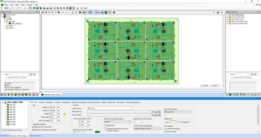
The selected CAD layers are automatically exported as Gerber and linked to the board, immediately creating a realistic and complete view of the PCB and panel. Using the OIB connector, the creation of nested panels and family boards is also easily possible.
These special features are not inherently possible via the export of a “.QD” file, but even here a placement angle correction can be manually defined per part number, and Gerber data can be generated in addition to the “.QD” file.
By using PCB-Investigator you save time and increase precision when creating placement programs. The automatic calculation of rotation angle and position correction with the OIB Connector, as well as the transfer of placement markers ensure a smooth and error-free production of your PCBs!
Downloads/Links