Calculate the capacitance of your high-frequency PCBs with the PCB-Investigator – Convincing advantages over other tools!

When manufacturing printed circuit boards with high-frequency bus systems such as DDR4, ensuring signal integrity through impedance control of coupled bus traces is of high importance.
The PCB Investigator provides an easy way to calculate the capacitance between these bus traces and your ground signal.
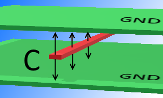
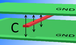
By selecting an impendance controlled net (or part of it) and the associated ground, PCB-Investigator calculates all intersecting areas in between and applies the plate capacitor formula for each intersecting area. The information about the structure must be entered beforehand in order to use the correct layer distances.
Coupled impendance controlled networks such as high frequency buses or clock signals should have the same capacity for grounding to ensure signal integrity.
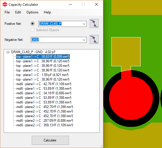
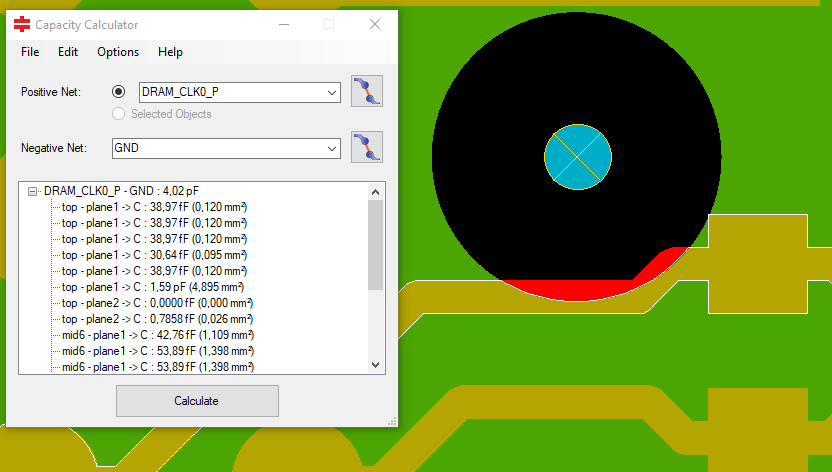
One of the most common causes of varying capacities and the resulting poor signal integrity can be attributed to the via openings in the grounding. If one of the bus signals touches or crosses these via openings, the track is no longer completely above ground as it was intended to be. Even a small overlap can result in a significant difference in capacity compared to the other bus lanes. This quickly has a bad impact on your signal integrity (see pictures).
Ensure the functional safety of your PCB design! Use the PCB Investigator’s capacity calculator for your layout review!
Downloads/Links


