
Changes are part of the development process for every printed circuit board. Components are moved, nets are adjusted, traces are modified, or test points are added. The key is to identify these changes reliably and assess them transparently during the design review.
PCB-Investigator provides several comparison functions for this purpose, each covering a different area: Graphic Board Compare, Database Comparison, and Instance Synchronization.
Why Professional Change Tracking Is So Important
The more complex a PCB becomes, the more difficult it is to identify changes with the naked eye. Even a small component shift, a modified net assignment, or an adjusted copper area can affect functionality, manufacturing, testing, or overall quality.
A systematic comparison helps answer questions such as:
- Which areas of the layout have changed?
- Which components have been added, removed, or modified?
- Have any nets or test access points changed?
- Are the differences relevant, or are they simply the result of minor geometric tolerances?
- How can the results be documented for future reviews?
PCB-Investigator offers both visual and data-based comparison options for these tasks.
Graphic Board Compare: Identify Geometric Changes
Graphic Board Compare focuses on the graphical differences between two PCB designs.
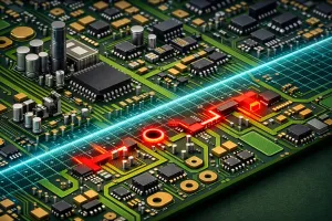
Changes to traces, pads, copper areas, and other layout objects are highlighted visually. This makes it easy to identify the exact areas in which the design has changed.
Very small differences that are not relevant to production can be hidden. This keeps the display clear and allows users to focus on the changes that actually matter.
The comparison results can also be exported and documented, for example in an interactive HTML report.
Database Comparison: Analyze Changes at Data Level
Not every relevant change is immediately visible in the layout. Database Comparison therefore compares the underlying PCB data.
The following areas can be analyzed, among others:
- Components,
- Nets,
- Test points and test access.
The results are displayed both as an overview and as a detailed change list. This list can include information such as reference designators, coordinates, values, attributes, and net names.
Filters and color-coded markings make it possible to select relevant changes more precisely and evaluate them more quickly.
Instance Synchronization: Review Two Designs in Parallel
Instance Synchronization allows two open PCB-Investigator instances to be connected. Navigation and views can be synchronized, enabling users to examine the same areas in both designs at the same time.
When users zoom in or navigate to a specific position in one instance, the second view follows accordingly. Differences between the designs can be highlighted and reviewed directly in the relevant layout context.
This function is particularly useful for interactive design reviews in which two layout versions need to be compared step by step.
Which Function Is Best Suited for Which Purpose?
The three functions examine changes from different perspectives:
Graphic Board Compare shows where the layout geometry has changed.
Database Comparison shows which components, nets, attributes, or test access points have changed.
Instance Synchronization is suitable for the parallel and interactive examination of two designs.
For the most comprehensive design review possible, the functions can be combined. Database Comparison first provides a structured overview, Graphic Board Compare shows the geometric impact, and Instance Synchronization then supports the detailed examination of individual areas.
Conclusion
The comparison functions in PCB-Investigator make it possible to identify design changes more quickly, assess them more precisely, and document them transparently.
As a result, design reviews become more efficient, coordination between development, layout, and quality assurance becomes easier, and potential sources of error can be identified at an earlier stage.